|
| |
| |
|---|
|
| |
| |
|---|
Truck Parts & Their Functions
Electrical System
| Item | Sample Picture | Function |
| Alternator | 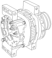 | The alternator is the electrical system's main source of power while the engine is running. It converts mechanical energy into direct current (DC) that is used to power the vehicle's electrical components and charge the batteries for starting. |
| Bulkhead Module (BHM) |  | The Bulkhead Module (BHM) is the primary module of the vehicle electrical system, and controls the operation of the other multiplex modules in the system and a variety of other vehicle components either directly or indirectly. The Bulkhead Module is mounted in an opening on the frontwall slightly below and outboard of the steering column. It has four harness connections on the engine compartment side of the frontwall and three harness connections on the cab side. Connections on the engine side are: the forward chassis harness, the engine harness, and two to the frontwall harnesses. Connections on the cab side include up to three dash harness connectors. |
| Chassis Module (CHM) |  | The Chassis Module (CHM) is the secondary module of the vehicle electrical system, and acts as a slave to the Bulkhead Module. The Chassis Module is mounted to the bracket that holds the transmission control unit on the outside of the left-hand frame rail just behind the front wheel well. It has five harness connections. |
| Expansion Module (EXM) |  | The Expansion Module (EXM) is an optional module of the vehicle electrical system, and acts as a slave to the Bulkhead Module. It is functionally equivalent to the Chassis Module (CHM). An EXM may be required on a vehicle in order to add non-standard functionality (such as heated mirrors) when all the required pins are already in use on the Chassis Module or on previously installed EXMs. Since it is optional, there may be from zero to five EXMs on a vehicle. The EXM has five harness connections, though all might not be used. |
| Instrumentation Control Unit (ICU) |  | The ICU3-M2 is a basic electronic dashboard that accepts input from the fuel level sensor, the transmission temperature sensor (if installed), the J1587 datalink, and the J1939 datalink. The information is processed by a micro-computer and displayed on electronic gauges driven by stepper motors. Only the air gauges operate mechanically. |
| Main Power Distribution Module (PDM) |  | The main power distribution module (PDM) is mounted under the hood on the left-hand front fender and distributes battery power to the vehicle control modules, including the Bulkhead Module, Chassis Module, Expansion Modules, and vehicle ECUs. The main PDM contains the fuses required to protect the power feed circuits to these modules. While the main PDM provides power to them, the modules themselves control power flow and circuit protection to the various components of the vehicle electrical systems. Because of this, traditional PDM devices such as relays and circuit breakers are no longer necessary on the main PDM. |
| Multifunction Turn Signal |  | The multifunction turn signal switch is mounted on the left-hand side of the steering column just below the steering wheel. The switch uses a low-current resistive ladder network for the switch functions. Low-current switches allow the use of smaller diameter wires and the resistive ladder network reduces the number of wires. Each switch function corresponds to a resistive output. The resistive ladder output is connected to the Instrumentation Control Unit (ICU3-M2) where the signals are processed and sent to the Bulkhead Module to actuate high-current devices such as the headlamps, turn signals, and wiper motor. The hazard switch is a traditional switch and is directly wired to the Bulkhead Module. |
| Multiplexing |  | The term "multiplexing" describes how the vehicle's electrical system works. Multiplexing is defined as sending multiple electronic messages through the same signal path at the same time—in this case, through the vehicle's wiring. Multiplexing allows a vehicle's electrical system to simultaneously perform tasks and to monitor components. A multiplexed system uses electronic control units (ECUs) to operate the system. The electrical system components, such as switches and lamps, are connected to the ECUs, which collect and control all information about the components by communicating on the datalink. A less formal description might be that multiplexing is much like the interstate highway system. Trucks and cars share the roadway, with each vehicle bound for a different destination. Every vehicle travels at different speeds, enters and exits at different places, and the occupants of every vehicle have different objectives. Whether it is a truck driver hauling goods from a factory to a store or a saleswoman heading home from work, highway users are like the electronic signals flashing along the datalink. |
| Smart Switches |  | Smart switches are optional low-current switches that are connected to the Bulkhead Module (BHM) or to an optional Switch Expansion Module (SEM) on an S2 chassis. A smart switch is used to activate an optional feature on the vehicle. These features may include, but are not limited to:
fog lights, differential lock control, interaxle lock control, PTO control, marker light interrupt control |
| Starter | 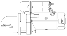 | The starter has a small starting gear that, when you turn the key or press the engine start button, engages the engine's flywheel. Then it delivers power, getting the engine rotating. This allows it to suck air and fuel into the cylinders and begin the combustion process that allows it to run on its own. |
| Switch Expansion Module (SEM) |  | The Switch Expansion Module (SEM) is an optional module of the vehicle electrical system, and acts as a slave to the Bulkhead Module (BHM). An SEM is used on a vehicle to add smart switches when all smart switch locations on the vehicle are already in use, or when installing a smart switch in a location that existing smart switch harnesses or modules cannot access, such as overhead. The SEM does not control any outputs. Since it is optional, there may be from zero to four SEMs on a vehicle. There can be up to six smart switches connected to each SEM. It has two harness connections, though both might not be used. |
| Vehicle Control Unit (VCU) |  | The Vehicle Control Unit (VCU) coordinates the components in the powertrain or even assumes some of their functions. This includes control of the inverter and battery management system as well as transmission and engine control. |
